Superchargers and Turbochargers
An obvious way to get more engine power is to increase an engine’s displacement. Allison V-1710 engines at the beginning of the war had 1,700 cubic inches of capacity. They produced about 1,000 horsepower…
Key Points
- Engine volume, high-octane fuel, and forced induction drove World War II engine performance growth
- Forced Induction
- As an aircraft flies higher, the air grows thinner and the engine loses power
- Forced induction pushes more air into the cylinders, allowing the plane to fly higher
- Forced induction pressure was actually higher than sea-level air pressure
- This increased power at all altitudes
- All fighters and bombers in World War II used forced induction
- There are two types of forced-induction devices
- Superchargers are powered mechanically by the engine
- This technology was proven by WWII
- Draws power from the engine, reducing the net gain
- Turbochargers are driven by the engine exhaust
- Power is largely “free”
- But pushed the state of the art in materials science in WWII, limiting availability
- Required extensive tubing and a heavy intercooler
- The P-40’s Allison V-1710 only had a one-stage supercharger
- This limited combat effectiveness to about 16,000 feet altitude
- Two-stage and two-speed superchargers allowed higher-altitude flight
- A one-stage, one-speed supercharger powerful enough for high altitude would blow the engine out at low altitude
- Two-stage superchargers (two impellers) and two-speed (or more) superchargers gave ranges of boost
- The U.S. Navy used two-stage superchargers in all of its production fighters
- F4F Wildcat, F6F Hellcat, F4U Corsair
- The U.S. Army Air Forces favored turbochargers for the second stage because the service focused on bombers, which had room for all the required tubing
- Turbochargers were tried but did not work on the P-40 or P-39, limiting their altitudes
- They worked on the P-38 because the two big nacelles had room for turbochargers
- They also worked in the bulky P-47 Thunderbolt
- The P-51 Mustang used British Merlins with two-stage and usually two-speed superchargers
Forced Induction
An obvious way to get more engine power is to increase an engine’s displacement. Allison V-1710 engines at the beginning of the war had 1,700 cubic inches of capacity. They produced about 1,000 horsepower. Toward the end of the war, the massive Pratt & Whitney R-2800 had 2,800 cubic inches of capacity and produced twice the early Allison’s power.
However, Stanley Hooker, who led the development of superchargers at Rolls-Royce, stressed that engine size alone is misleading when thinking about power. Equally critical is the ability to provide the engine with air and fuel effectively. This was done using forced induction and high-octane fuel. They gave what was effectively a larger engine displacement.
As altitude increases, the air grows thinner. At 18,000 feet, for example, air density is half of what it is at sea level. Lower air density is not entirely bad. It reduces air resistance, so level speed increases for a given engine power as an aircraft climbs. However, declining air density reduces the oxygen the engine needs to burn fuel. Up to some altitude, reduced air resistance is more important, and an aircraft’s level speed increases as altitude increases. Beyond this altitude, however, power loss dominates, and level speed decreases. This altitude is understandably called the “critical altitude.” Most quoted aircraft speeds are speeds at this critical altitude.
To compensate for reduced air density at higher altitudes, aircraft engines in World War II used forced induction, which compressed the air before mixing it with fuel. Thinning air would eventually win out. However, the aircraft’s new critical altitude was considerably higher thanks to forced induction, and performance at altitude was considerably better.
But why stop at sea-level air pressure? Forcing even more air into the cylinders would allow more fuel to be fed in as well, increasing engine power beyond its natural sea-level value. This would boost engine performance even at low altitudes. At standard temperature (59 degrees Fahrenheit), air pressure is 15 pounds per square inch. Forced induction in World War II produced up to twice this manifold pressure, forcing twice as much air into the engine. Of course, engines had to be built much stronger to deal with the higher power, and engines needed gasoline that was 100 octane or higher.
Forced Induction Cycle
Figure 1 shows how forced induction works. The forced induction device has a rapidly spinning impeller that sucks in ambient air. The impeller accelerates the incoming air centrifugally, from the center to the edge of the chamber. Although the air at the rim is moving very quickly — close to the speed of sound — it does not increase in pressure or temperature. At the edge of the chamber, fixed diffuser vanes slow the air, as Figure 2 illustrates. As the air slows, its pressure increases, following Bernoulli’s principle. The air now has the higher density the engine needs.


The Intercooler
In accordance with the Ideal Gas Law, however, the denser air is also hotter. If this hot air is mixed with gasoline and fed directly into the cylinder, the engine might be able to handle it. However, beyond some point, the hot charge will detonate prematurely, reducing engine efficiency or even damaging the engine. If detonation occurs, the air must be cooled before it reaches the carburetor, manifold, and pistons. There are three ways to do this.
If the detonation problem is not too great, the aircraft can use higher-octane gasoline. (In automobiles today, if you use gasoline with too low of an octane rating, your engine might knock. This is detonation.) In the 1930s, a typical rating for aviation gasoline was 87 octane. Many countries continued to use 87-octane gas during the war. Thanks to pre-war work at Shell Oil that involved Jimmy Doolittle, the United States entered the war with 100-octane avgas, although producing and distributing this high-quality fuel to combat units often fell behind needs. Theoretically, gasoline cannot go above 100 octane, which is effectively pure octane. However, performance can still be increased by adding other substances. The United States produced a considerable amount of 130 “performance number” gasoline during the war.
A more comprehensive way to reduce detonation is to use an intercooler, which is essentially a radiator. Figure 3 shows that the intercooler sits between the forced induction device and the engine. Radiators are heavy, and an intercooler requires the addition of tubing between the three devices involved.

One way to reduce detonation for brief periods of time was water injection. Water (usually mixed with methanol) was injected into the engine with the air/fuel charge. This reduced the temperature considerably, making the air even denser. However, the added coolant disrupted combustion to some extent. The charge did not burn completely, and the exhaust contained black smoke. This disruption must be very brief or the engine would stop working. Consequently, water injection was used only for brief periods of time, such as take-off or emergency combat boost.
Superchargers and Turbochargers
There are two types of forced induction devices. They differ in how the impeller’s rotation is powered. The first is the supercharger, in which the engine itself powers the impeller via a short drive shaft. Figure 4 shows that the supercharger usually presses directly against the engine.
The second type of forced induction device is the turbocharger, which is also called a turbo-supercharger. In turbos, the impeller is powered by the engine’s exhaust. High-performance aircraft engines produce very hot, fast, high-pressure exhaust gas. The exhaust spins a turbine, which drives the impeller. (With engines that did not use turbochargers, it was common to direct the exhaust backward, giving extra thrust that might boost the aircraft’s forward speed by five miles an hour or more.)

In theory, turbochargers are better than superchargers. A supercharger “steals” power from the engine, lessening its benefit. For example, if a supercharger increases engine performance by 200 horsepower but requires 50 horsepower from the engine to drive its impeller, the net gain will only be 150 horsepower. In contrast, the exhaust gas that drives turbochargers is essentially free energy. This is not entirely true, but back pressure from the turbine does not substantially reduce engine power. This is why modern cars use turbochargers instead of superchargers. (As air pressure decreases, in fact, back pressure from the atmosphere itself decreases; the exhaust actually becomes faster as altitude increases.)
Unfortunately, it is difficult to handle pressurized, fast, and very hot exhaust gas. Special materials were needed, and these were underdeveloped during World War II. Turbocharger production was difficult throughout the war, and reliability was a frequent issue. World War II was a few years too early for turbos in terms of materials science.
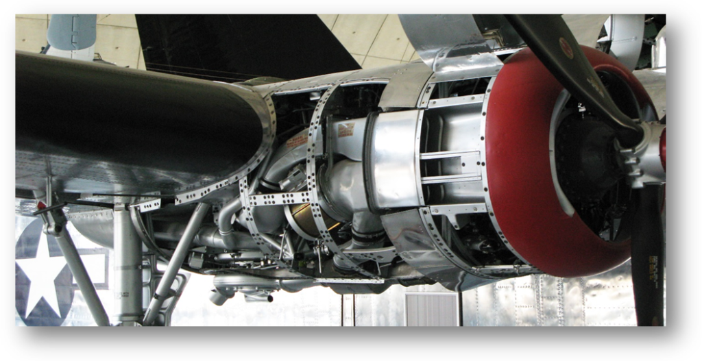
Turbochargers also require a great deal of heavy tubing to contain the hot gas flows. This tubing carries the hot engine exhaust to the turbocharger and delivers the compressed air back to the engine. When an intercooler is used, the amount of plumbing increases considerably. In a bomber, there is room for this piping. In fighters, the amount of piping needed is a serious design issue. Figure 5 illustrates the large and complex piping in a turbocharged bomber engine.
Speeds and Stages
All combat aircraft in World War II used superchargers. However, a single stage of supercharging was effective only up to about 16,000 feet. One solution was to use two stages of supercharging. Each stage had its own impeller, diffuser, and horn. These were placed in series, the first stage feeding into the second. At lower altitude, one second stage was bypassed by the pilot to prevent overboost. As the first stage became insufficient during a climb, that stage was kicked back into the flow.
Although combat aircraft all used supercharging for the first stage of forced induction, some used a turbocharger for their second stage. Given production difficulties, turbocharging was much more expensive. Also, while two stages of supercharging were sometimes possible without an intercooler, turbocharging almost always required an intercooler.
Another way to deal with the need for very different pressure boosts at lower and higher altitudes was to give superchargers multiple speeds. This required a gear and clutch assembly controlled by the pilot. Some British Merlin superchargers had three speeds. The German DB 601 and DB 605 engines used in most Bf 109s carried this trend to the logical extreme. Using fluid coupling with the engine, their superchargers could vary boost smoothly over a considerable range. These adjustments, furthermore, were handled automatically by a barometric-based control. This freed the fighter pilot to concentrate on his opponent.
Of course, having two or more speeds does not rule out also having two stages. Some of the later Merlin engines had two supercharger stages, each with three speeds. For the Fw 190, the BMW 801R under development at the end of the war had a two-stage, four-speed supercharger.
Uses in American Aircraft
F4F WITH A 2-STAGE, 1-SPEED SUPERCHARGED PRATT & WHITNEY R-1830 ENGINE
The first fighter in the world to use a two-stage supercharger was the Grumman F4F-3 Wildcat, which used the Pratt & Whitney R-1830 Twin Wasp radial engine. The unsuccessful XF4F-2 prototype used the R-1830-66 engine with a single-stage supercharger. Its performance was not good enough. For the F4F-3, Grumman switched to the R-1830-76 and R-1830-86 engines. Both had two-stage superchargers. This allowed all production Wildcats to perform at high altitudes from the beginning of the war in the Pacific. The heavy F4F burned copious amounts of fuel getting up to altitude, but in combat, altitude is life. From the first combat between Wildcats and Zeroes at Coral Sea to the battles in November at Guadalcanal, postwar analysis found that the F4F had a roughly 1:1 kill ratio against the vaunted Zero [Tillman 2001].

Merlins and Spitfires
Although we focus on American aircraft, the British Merlin engine’s evolution exemplifies how rapidly forced induction improved during the war. In addition, of course, the American P-51 Mustang became a great fighter only after it received license-built British Merlin engines.
Rolls-Royce Merlins, which were named after a type of falcon rather than the magician, had 1,650 cubic inches of capacity. This made them slightly smaller than Allison V-1710s. In addition, Merlins had 12 cylinders in a V configuration, while Allisons had 10. In general, barring supercharging, they were very comparable. However, supercharging made all the difference in the world.
In England, the Merlin engines that powered the Battle of Britain Spitfires had single-stage, single-speed superchargers. It was not until the Merlin Mk XX that a second speed was added, but not a second stage. When Stanley Hooker took over supercharger design at Rolls-Royce, he realized that air flows in the existing Merlin superchargers were imperfect. He improved them, and this resulted in a new single-stage two-speed supercharger for the Merlin Mk 45.[1] This new design allowed output to be raised to 1,515 hp at 11,000 feet. The Royal Air Force put this new engine into the Spitfire Mk V airframe just in time to battle the new Bf 109F, which began to appear in large numbers in early 1941. Compared to the Battle of Britain Bf 109E, the “Fredrick” had a completely redesigned wing and cooling system. It had improved fuselage aerodynamics and a somewhat more powerful engine.
The arrival of the Fw 190 in late 1941 made even these engines obsolete. Fortunately, Rolls-Royce was ready with a two-stage, two-speed supercharger for its engines, beginning with the Mk 60 series. These engines powered the Spitfire Mk IX, which restored British parity with the best German fighters. These two-stage supercharged Merlins came considerably later than the two-stage R-1830. In compensation, this delay allowed the Mk 60 and engines to have not only two stages but also two speeds and eventually three speeds for greater pilot control.
The P-40
Before the war, the U.S. Army Air Forces were enamored with turbocharging for the second stage of forced induction, even for fighters. Before the P-40, the Army had Allison add a turbocharged second stage to its V-1710. Curtis used this engine in its XP-37 prototype. As Figure 7 shows, adding room for the turbocharger and its tubing led to an enormously long nose. In fact, the XP-37 looked more like a child’s cartoon than a military aircraft. Its long nose turned ordinary takeoffs and landings into near-death experiences. In combat, pulling lead on a target would have been nearly impossible because the target would be obscured by the nose during sharp turns. In any case, the turbocharger proved unreliable. A similar project to put a turbocharger in the P-39 prototype also floundered because of poor reliability.

Curtis then redesigned the aircraft to work with the original V-1710 with only its single-stage, single-speed supercharger. Even before the war began for the United States, we realized that our P-40s lacked the high-altitude performance that European combat had proven to be critical. As some pilots put it, the P-40 was afraid of heights. American Warhawk pilots at the start of the war knew that they would probably have to endure an initial attack from above in a dog fight. The same was true of Bell P-39s. In the Cactus Air Force on Guadalcanal, USAAF P-39s and Navy F4Fs often flew together, with the P-39s doing ground attacks while F4Fs flew high cover.
Late in the war, two versions of the P-40 Warhawk did receive Packard-built Merlin engines. These were the P-40F and the P-40L. Unfortunately, neither received versions of the Merlin with two-stage superchargers. They only received Merlin 28s Merlin 31s, which were license-built by Packard as the V-1650-1. These single-stage superchargers at least had two speeds. They were nothing like the Mustang’s Packard V-1650-3 and V-1650-7 engines, although their moderately greater performance was appreciated. In any case, only about 1,000 of these Packard-engined Warhawks were built, relegating them to a footnote.

Giving P-40s the two-stage supercharged engines that the Mustang received would have created a better airplane, but the P-51 had a far superior airframe with laminar flow wings. A P-40 with the same engine would still not be competitive with German opponents. By this time in the war, the P-40 was being used primarily for ground attack anyway, so while an increase in higher-altitude performance might have been nice, it was not as critical as it was in the Mustang, which shouldered the air-superiority duty. The P-51 was understandably allocated the scarce two-stage Packards.
P-38s with Turbocharger second stages
Perhaps the Army was looking to the future, knowing that its P-38s would finally arrive “soon.” As Figure 9 illustrates, the two big nacelles on this advanced but costly fighter had room for a turbocharger and its piping. The two engines allowed the Lightning to perform very well despite its weight. Unfortunately, P-38s did not arrive in the Pacific until late in 1942 and did not become fully operational in numbers until early 1943. When they did, however, they gave the Army a fighter that could take on the Zero at altitude.

P-51 Mustangs with LICENSED High-Altitude Merlin Engines
The P-51 Mustang originally flew with an Allison V-1710, but this engine was almost immediately replaced by two-stage license-built Merlin engines. Army pilots finally got a fighter that could fight very well at high altitudes. The Packard V-1650-3 and V-1650-7, which were U.S.-built versions of the Merlin 68 and 69, produced 1,670 hp and had a boost of 18 psi. The Mustang proved to be a war winner.

The Republic P-47 Thunderbolt’s Use of Turbocharging
For the P-47, which came out about the same time as the P-51, Republic took a very different approach. First, instead of using a liquid-cooled engine like other Army fighters, the Republic used the massive new Pratt & Whitney R-2800 Double Wasp air-cooled engine. Second, it used turbocharging for its second stage of forced induction. Most P-47s used the R-2800-59W with a GE C-23 turbocharger. The W indicated water injection.
As noted earlier, a turbocharger and its tubing consume a lot of room. This led to the fighter’s rotund body shape. The turbocharger itself sat at the bottom of the aircraft, toward the rear. Figure 11 shows the turbocharger’s vent for spent exhaust air. The P-47 was fast, but it took a brute-force approach to speed, and although it achieve many kills, the big “Jug” was best for ground attack.

The Vought F4U Corsair
The F4U Corsair, which used the same engine as the P-47, was much more svelte. Instead of using turbocharging for the second state of forced induction, all production versions of the Corsair used two-stage supercharging. Except in the final months of the war, Corsairs used the R-2800-8 or the R-2800-8W with water injection. With no need for massive turbocharging tubing, the Corsair had a slim profile. The two-stage supercharger was not, however, the reason for the Corsair’s long nose, as some sources claim. When more guns were added to the wings early in the bent-wing bird’s development, there was no longer room for wing fuel tanks. A bigger fuel tank had to be added to the fuselage. This was placed between the pilot and the engine, near the center of gravity. Given the size of the fuel tank, the nose became considerably longer.

F6F Hellcats
Like the F4U Corsair, the Grumman F6F Hellcat used the Pratt & Whitney R-2800 engine. Also like the Corsair, the Hellcat used a two-stage supercharger for its production versions, the F6F-3 and F6F-5. In two prototypes, the XF6F-2 and the XF6F-4, Grumman tried a single-stage supercharger plus a turbocharger. Neither proved satisfactory.

“Hellcats F6F-3, May 1943” by USN; Original uploader was “Felix c” at en.wikipedia -Originally from en.wikipedia; description page is/was here; U.S. Navy National Museum of Naval Aviation photo No. 2011.003.274.018. Licensed under Public Domain via Wikimedia Commons – https://commons.wikimedia.org/wiki/File:Hellcats_F6F-3,_May_1943.jpg#mediaviewer/File:Hellcats_F6F-3,_May_1943.jpg.
Perspective
At the beginning of World War II, single-stage, single-speed superchargers were the norm for fighters. By the end, two-stage, three-speed superchargers were being used, and some fighters used turbochargers for the second stage. Engines had to be continuously strengthened to take the growing power generated by superchargers, and higher-octane gas became critical. In America, bombers typically used supercharging for the first stage and turbocharging for the second.
How forced-induction piston engines might have evolved after the war will never be known. Jet engines took over in both fighters and bombers. Like many other technologies at the end of World War II, forced induction had no more history to live. At the same time, jet engines needed compressors in their front sections to drive a high-pressure fuel-air charge into combustion chambers. These compressors have essentially the same role as turbochargers. In addition, these compressors were driven by turbines placed in the hot and fast exhaust of the jet engine. Turbines provided the same function in turbochargers. It is not surprising that GE, which was effectively America’s only turbocharger manufacturer during World War II, was an early leader in jet propulsion.
Sources
Bent, Ralph D. and McKinley, James L., Aircraft Powerplants, 5th Edition, McGraw-Hill, 1985.
Caden, Martin and Johnson, Robert, Thunderbolt, P-47, Kindle Edition, iBooks, 2010.
Christopher, John, The Race for Hitler’s X-Planes Britain’s 1945 Mission to Capture Secret Luftwaffe Technology, History Press, 2013.
Connors, Jack, The Engines of Pratt & Whitney: A Technical History, AIAA, 2009.
Daily, James W. and Harleman, Donald R. F., Fluid Dynamics, Addison-Wesley, 1966.
D’Angina, James, Vought F4U Corsair, Osprey, 2014.
Edgars, Julian, A Guide to Turbos and Superchargers: A Comprehensive Guide to Forced Induction, Clockwork Media Pty Ltd., 2001.
Gunston, Bill, Development of Piston Aero Engines, 2nd ed., Haynes Publishing, 2006.
Tillman, Barrett, Hellcat: The F6F in World War II, US Naval Institute Press, 1979.
Tillman, Barrett, Wildcat: The F4F in World War II, 2nd ed., US Naval Institute Press, 2001.
Von Mises, Richard and Friedrichs, K. O., Fluid Dynamics, Springer-Verlag.
White, Graham, Allied Aircraft Piston Engines of World War II: History and Development of Frontline Aircraft Piston Engines Produced by Great Britain and the United States, Society of Automotive Engineers, 1995.
Williams, Mike and Stirling, Neil, WWIIaircraftperformance.org, last viewed January 2015.
Whitney, Daniel D., Vee’s For Victory! The Story of the Allison V-1710 Aircraft Engine 1929-1948, Atglen, PA: Schiffer Military History, 1998.
Wisniewski, Jason R., Powering the Luftwaffe: German Aero Engines of World War II, FriesenPress, 2013.